Monday, October 10, 2011

ld-http.so

In the last decade we have enjoyed a renaissance of programming language development. Clojure, Scala, Python, C#/F#/et al, Ruby (and Rails), Javascript, node.js, Haskell, Go, and the list goes on. Development of many of those languages started in the 1990s, but adoption accelerated in the 2000s.

Why now? There are probably a lot of reasons, but I want to opine on one.

HTTP is our program linker.

We no longer have to worry about linking to a gazillion libraries written in different languages, with all of the compatibility issues that entails. We no longer build large software systems by linking it all into ginormous binaries, and that loosens a straightjacket which made it difficult to stray too far from C. We dabbled with DCE/CORBA/SunRPC as a way to decouple systems, but RPC marshaling semantics still dragged in a bunch of assumptions about data types.

It took the web and the model of software as a service running on server farms to really decompose large systems into cooperating subsystems which could be implemented any way they like. Facebook can implement chat in Erlang, Akamai can use Clojure, Google can mix C++ with Java/Python/Go/etc. It is all connected together via HTTP, sometimes carrying SOAP or other RPCs, and sometimes with RESTful interfaces even inside the system.


Friday, October 7, 2011

Finding Ada, 2011

Ada Lovelace Day aims to raise the profile of women in science, technology, engineering and maths by encouraging people around the world to talk about the women whose work they admire. This international day of celebration helps people learn about the achievements of women in STEM, inspiring others and creating new role models for young and old alike.

For Ada Lovelace Day 2010 I analyzed a patent for a frequency hopping control system for guided torpedoes, granted to Hedy Lamarr and George Antheil. For Ada Lovelace Day this year I want to share a story from early in my career.

After graduation I worked on ASICs for a few years, mostly on Asynchronous Transfer Mode NICs for Sun workstations. In the 1990s Sun made large investments in ATM: designed its own Segmentation and Reassembly ASICs, wrote a q.2931 signaling stack, adapted NetSNMP as an ILMI stack, wrote Lan Emulation and MPOA implementations, etc.

Yet ATM wasn't a great fit for carrying data traffic. Its overhead for cell headers was very high, it had an unnatural fondness for Sonet as its physical layer, and it required a signaling protocol far more complex than the simple ARP protocol of Ethernet.

Cell loss == packet loss.Its most pernicious problem for data networking was in dealing with congestion. There was no mechanism for flow control, because ATM evolved out of a circuit switched world with predictable traffic patterns. Congestive problems come when you try to switch packets and deal with bursty traffic. In an ATM network the loss of a single cell would render the entire packet unusable, but the network would be further congested carrying the remaining cells of that packet's corpse.

Allyn Romanow at Sun Microsystems and Sally Floyd from the Lawrence Berkeley Labs conducted a series of simulations, ultimately resulting in a paper on how to deal with congestion. If a cell had to be dropped, drop the rest of the cells in that packet. Furthermore, deliberately dropping packets early as buffering approached capacity was even better, and brought ATM links up to the same efficiency for TCP transport as native packet links. Allyn was very generous with her time in explaining the issues and how to solve them, both in ATM congestion control and in a number of other aspects of making a network stable.

ATM also had a very complex signaling stack for setting up connections, so complex that many ATM deployments simply gave up and permanently configured circuits everywhere they needed to go. PVCs only work up to a point, the network size is constrained by the number of available circuits. Renee Danson Sommerfeld took on the task of writing a q.2931 signaling stack for Solaris, requiring painstaking care with specifications and interoperability testing. Sun's ATM products were never reliant on PVCs to operate, they could set up switched circuits on demand and close them when no longer needed.

In this industry we tend to celebrate engineers who spend massive effort putting out fires. What I learned from Allyn, Sally, and Renee is that the truly great engineers see the fire coming, and keep it from spreading in the first place.

Update: Dan McDonald worked at Sun in the same timeframe, and posted his own recollections of working with Allyn, Sally, and Renee. As he put it on Google+, "Good choices for people, poor choice for technology." (i.e. ATM Considered Harmful).


Wednesday, October 5, 2011

Non Uniform Network Access

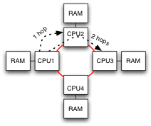
Four CPUs in a ring, with RAM attached to each.Non Uniform Memory Access is common in modern x86 servers. RAM is connected to each CPU, which connect to each other. Any CPU can access any location in RAM, but will incur additional latency if there are multiple hops along the way. This is the non-uniform part: some portions of memory take longer to access than others.

Yet the NUMA we use today is NUMA in the small. In the 1990s NUMA aimed to make very, very large systems commonplace. There were many levels of bridging, each adding yet more latency. RAM attached to the local CPU was fast, RAM for other CPUs on the same board was somewhat slower. RAM on boards in the same local grouping took longer still, while RAM on the other side of the chassis took forever. Nonetheless this was considered to be a huge advancement in system design because it allowed the software to access vast amounts of memory in the system with a uniform programming interface... except for performance.

Operating system schedulers which had previously run any task on any available CPU would randomly exhibit extremely bad behavior: a process running on distant combinations of CPU and RAM would run an order of magnitude slower. NUMA meant that all RAM was equal, but some was more equal than others. Operating systems desperately added notions of RAM affinity to go along with CPU and cache affinity, but reliably good performance was difficult to achieve.

As an industry we concluded that NUMA in moderation is good, but too much NUMA is bad. Those enormous NUMA systems have mostly lost out to smaller servers clustered together, where each server uses a bit of NUMA to improve its own scalability. The big jump in latency to get to another server is accompanied by a change in API, to use the network instead of memory pointers.


A Segue to Web Applications

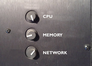
Tuning knobs for CPU, Memory, Network.

Modern web applications can make tradeoffs between CPU utilization, memory footprint, and network bandwidth. Increase the amount of memory available for caching, and reduce the CPU required to recalculate results. Shard the data across more nodes to reduce the memory footprint on each at the cost of increasing network bandwidth. In many cases these tradeoffs don't need to be baked deep in the application, they can be tweaked via relatively simple changes. They can be adjusted to tune the application for RAM size, or for the availability of network bandwidth.


Further Segue To Overlay Networks

There is a lot of effort being put into overlay networks for virtualized datacenters, to create an L2 network atop an L3 infrastructure. This allows the infrastructure to run as an L3 network, which we are pretty good at scaling and managing, while the service provided to the VMs behaves as an L2 network.

Yet once the packets are carried in IP tunnels they can, through the magic of routing, be carried across a WAN to another facility. The datacenter network can be transparently extended to include resources in several locations. Transparently, except for performance. The round trip time across a WAN will inevitably be longer than the LAN, the speed of light demands it. Even for geographically close facilities the bandwidth available over a WAN will be far less than the bandwidth available within a datacenter, perhaps orders of magnitude less. Application tuning parameters set based on the performance within a single datacenter will be horribly wrong across the WAN.

I've no doubt that people will do it anyway. We will see L2 overlay networks being carried across VPNs to link datacenters together transparently (except for performance). Like the OS schedulers suddenly finding themselves in a NUMA world, software infrastructure within the datacenter will find itself in a network where some links are more equal than others. As an industry, we'll spend a couple years figuring out whether that was a good idea or not.


footnote: this blog contains articles on a range of topics. If you want more posts like this, I suggest the Ethernet label.

Sunday, October 2, 2011

NVGRE Musings

It is an interesting time to be involved in datacenter networking. There have been announcements recently of two competing proposals for running virtual L2 networks as an overlay atop a underlying IP network, VXLAN and NVGRE. Supporting an L2 service is important for virtualized servers, which need to be able to move from one physical server to another without changing their IP address or interrupting the services they provide. Having written about VXLAN in a series of three posts, now it is time for NVGRE. Ivan Pepelnjak has already posted about it on IOShints, which I recommend reading.

NVGRE encapsulates L2 frames inside tunnels to carry them across an L3 network. As its name implies, it uses GRE tunneling. GRE has been around for a very long time, and is well supported by networking gear and analysis tools. An NVGRE Endpoint uses the Key field in the GRE header to hold the Tenant Network Identifier (TNI), a 24 bit space of virtual LANs.

Outer MAC, Outer IP, GRE, Inner MAC, Inner Payload, Outer FCS.

The encapsulated packet has no Inner CRC. When VMs send packets to other VMs within a server they do not calculate a CRC, one is added by a physical NIC when the packet leaves the server. As the NVGRE Endpoint is likely to be a software component within the server, prior to hitting any NIC, the frames have no CRC. This is another case where even on L2 networks, the Ethernet CRC does not work the way our intuition would suggest.

The NVGRE draft refers to IP addresses in the outer header as Provider Addresses, and the inner header as Customer Addresses. NVGRE can optionally also use an IP multicast group for each TNI to distribute L2 broadcast and multicast packets.


Not Quite Done

As befits its "draft" designation, a number of details in the NVGRE proposal are left to be determined in future iterations. One largish bit left unspecified is mapping of Customer Addresses to Provider. When an NVGRE Endpoint needs to send a packet to a remote VM, it must know the address of the remote NVGRE Endpoint. The mechanism to maintain this mapping is not yet defined, though it will be provisioned by a control function communicating with the Hypervisors and switches.


Optional Multicast?

The NVGRE draft calls out broadcast and multicast support as being optional, only if the network operator chooses to support it. To operate as a virtual Ethernet network a few broadcast protocols are essential, like ARP and IPv6 ND. Presumably if broadcast is not available, the NVGRE Endpoint would respond to these requests to its local VMs.

Yet I don't see how that can work in all cases. The NVGRE control plane can certainly know the Provider Address of all NVGRE Endpoints. It can know the MAC address of all guest VMs within the tenant network, because the Hypervisor provides the MAC address as part of the virtual hardware platform. There are notable exceptions where guest VMs use VRRP, or make up locally administered MAC addresses, but I'll ignore those for now.

I don't see how an NVGRE Endpoint can know all Customer IP Addresses. One of two things would have to happen:

  • Require all customer VMs to obtain their IP from the provider. Even backend systems using private, internal addresses would have to get them from the datacenter operator so that NVGRE can know where they are.
  • Implement a distributed learning function where NVGRE Endpoints watch for new IP addresses sent by their VMs and report them to all other Endpoints.

The current draft of NVGRE makes no mention of either such function, so we'll have to watch for future developments.

The earlier VL2 network also did not require multicast and handled ARP via a network-wide directory service. Many VL2 concepts made their way into NVGRE. So far as I understand it, VL2 assigned all IP addresses to VMs and could know where they were in the network.


Multipathing

Load balancing across four links between switches.An important topic for tunneling protocols is multipathing. When multiple paths are available to a destination, either LACP at L2 or ECMP at L3, the switches have to choose which link to use. It is important that packets on the same flow stay in order, as protocols like TCP use excessive reordering as an indication of congestion. Switches hash packet headers to select a link, so packets with the same headers will always choose the same link.

Tunneling protocols have issues with this type of hashing: all packets in the tunnel have the same header. This limits them to a single link, and congests that one link for other traffic. Some switch chips implement extra support for common tunnels like GRE, to include the Inner header in the hash computation. NVGRE would benefit greatly from this support. Unfortunately, it is not universal amongst modern switches.
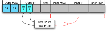
Choosing Provider Address by hashing the Inner headers.The NVGRE draft proposes that each NVGRE Endpoint have multiple Provider Addresses. The Endpoints can choose one of several source and destination IP addresses in the encapsulating IP header, to provide variance to spread load across LACP and ECMP links. The draft says that when the Endpoint has multiple PAs, each Customer Address will be provisioned to use one of them. In practice I suspect it would be better were the NVGRE Endpoint to hash the Inner headers to choose addresses, and distribute the load for each Customer Address across all links.

Using multiple IP addresses for load balancing is clever, but I can't easily predict how well it will work. The number of different flows the switches see will be relatively small. For example if each endpoint has four addresses, the total number of different header combinations between any two endpoints is sixteen. This is sixteen times better than having a single address each, but it is still not a lot. Unbalanced link utilization seems quite possible.


Aside: Deliberate Multipathing

One LACP group feeding in to the next.The relatively limited variance in headers leads to an obvious next step: ensure the traffic will be balanced by predicting what the switch will do, and choose Provider IP addresses to optimize and ensure it is well balanced. In networking today we tend to solve problems by making the edges smarter.

The NVGRE draft says that selection of a Provider Address is provisioned to the Endpoint. Each Customer Address will be associated with exactly one Provider Address to use. I suspect that selection of Provider Addresses is expected to be done via an optimization mechanism like this, but I'm definitely speculating.

I'd caution that this is harder than it sounds. Switches use the ingress port as part of the hash calculation. That is, the same packet arriving on a different ingress port will choose a different egress link within the LACP/ECMP group. To predict behavior one needs a complete wiring diagram of the network. In the rather common case where several LACP/ECMP groups are traversed along the way to a destination, the link selected by each previous switch influences the hash computation of the next.


Misc Notes

  • The NVGRE draft mentions keeping an MTU state per Endpoint, to avoid fragmentation. Details will be described in future drafts. NVGRE certainly benefits from a datacenter network with a larger MTU, but will not require it.
  • VXLAN describes its overlay network as existing within a datacenter. NVGRE explicitly calls for spanning across wide area networks via VPNs, for example to connect a corporate datacenter to additional resources in a cloud provider. I'll have to cover this aspect in another post, this post is too long already.


Conclusion

Its quite difficult to draw a conclusion about NVGRE, as so much is still unspecified. There are two relatively crucial mapping functions which have yet to be described:

  • When a VM wants to contact a remote Customer IP and sends an ARP Request, in the absence of multicast, how can the matching MAC address be known?
  • When the NVGRE Endpoint is handed a frame destined to a remote Customer MAC, how does it find the Provider Address of the remote Endpoint?

So we'll wait and see.


footnote: this blog contains articles on a range of topics. If you want more posts like this, I suggest the Ethernet label.

Monday, September 26, 2011

Peer Review Terminology

Many companies now include peer feedback as part of the annual review process. Each employee nominates several of their colleagues to write a review of their work from the previous year. If you are new to this process, here is some terminology which may be useful.

peerrihelion
[peer-ree-heel-yun] (noun)
The point at which 50% of requested peer reviews are complete.
peersuasion
[peer-swey-zhuhn] (noun)
A particularly glowing peer review.
peerjury
[peer-juh-ree] (noun)
An astonishingly glowing peer review.
peerplexed
[peer-plekst] (adjective)
What exactly did they work on, anyway?
peerrational
[peer-rash-uh-nl] (adjective)
Why am I reviewing this person?
peergatory
[peer-guh-tohr-ee] (noun)
The set of peer reviews which may have to be declined due to lack of time.
peerfectionist
[peer-fek-shuh-nist] (noun)
I spent a long time obsessing over wording.
peeriodic
[peer-ee-od-ik] (adjective)
Maybe I'll just copy some of what I wrote last year.
peerritation
[peer-ree-tay-shun] (noun)
Unreasonable hostility felt toward the subject of the last peer review left to be written.
peersecute
[peer-seh-kyoot] (verb)
How nice, everyone asked for my review.
peersona non grata
[peer-soh-nah nohn grah-tah] (noun)
Nobody asked for my review?
peeregular
[peer-reg-gyu-ler] (adjective)
An incomplete peer review, submitted anyway, just before the deadline.

Sunday, September 18, 2011

VXLAN Conclusion

This is the third and final article in a series about VXLAN. I recommend reading the first and second articles before this one. I have not been briefed by any of the companies involved, nor received any NDA information. These articles are written based on public statements and discussions available on the web.


Foreign Gateways

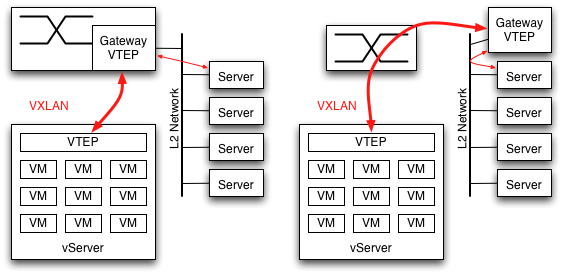
Though I've consistently described VXLAN communications as occurring between VMs, many datacenters have a mix of virtual servers with single-instance physical servers. Something has to provide the VTEP function for all nodes on the network, but it doesn't have to be the server itself. A Gateway function can bridge to physical L2 networks, and with representatives of several switch companies as authors of the RFC this seems likely to materialize within the networking gear itself. The Gateway can also be provided by a server sitting within the same L2 domain as the servers it handles.

Gateway to communicate with other physical servers on an L2 segment.

Even if the datacenter consists entirely of VMs, a Gateway function is still needed in the switch. To communicate with the Internet (or anything else outside of their subnet) the VMs will ARP for their next hop router. This router has to have a VTEP.


Transition Strategy

Mixture of VTEP-enabled servers with non requires a gateway function somewhereI'm tempted to say there isn't a transition strategy. Thats a bit too harsh in that the Gateway function just described can serve as a proxy, but its not far from the mark. As described in the RFC, the VTEP assumes that all destination L2 addresses will be served by a remote VTEP somewhere. If the VTEP doesn't know the L3 address of the remote node to send to, it floods the packet to all VTEPs using multicast. There is no provision for direct L2 communication to nodes which have no VTEP. It is assumed that an existing installation of VMs on a VLAN will be taken out of service, and all nodes reconfigured to use VXLAN. VLANs can be converted individually, but there is no provision operation with a mixed set of VTEP-enabled and non-VTEP-enabled nodes on an existing VLAN.

For an existing datacenter which desires to avoid scheduling downtime for an entire VLAN, one transition strategy would use a VTEP Gateway as the first step. When the first server is upgraded to use VXLAN and have its own VTEP, all of its packets to other servers will go through this VTEP Gateway. As additional servers are upgraded they will begin communicating directly between VTEPs, and rely on the Gateway to maintain communication with the rest of their subnet.

Where would the Gateway function go? During the transition, which could be lengthy, the Gateway VTEP will be absolutely essential for operation. It shouldn't be a single point of failure, and this should trigger the network engineer's spidey sense about adding a new critical piece of infrastructure. It will need to be monitored, people will need to be trained in what to do if it fails, etc. Therefore it seems far more likely that customers will choose to upgrade their switches to include the VTEP Gateway function, so as not to add a new critical bit of infrastructure.


Controller to the Rescue?

Mixture of VTEP-enabled servers with non requires a gateway function somewhereWhat makes this transition strategy difficult to accept is that VMs have to be configured to be part of a VXLAN. They have to be assigned to a particular VNI, and that VNI has to be given an IP multicast address to use for flooding. Therefore something, somewhere knows the complete list of VMs which should be part of the VXLAN. In Rumsfeldian terms, there are only known unknown addresses and no unknown unknowns. That is, the VTEP can know the complete list of destination MAC addresses it is supposed to be able to reach via VXLAN. The only unknown is the L3 address of the remote VTEP. If the VTEP encounters a destination MAC address which it doesn't know about, it doesn't have to assume it is attached to a VTEP somewhere. It could know that some MAC addresses are reached directly, without VXLAN encapsulation.

The previous article in this series brought up the reliance on multicast for learning as an issue, and suggested that a VXLAN controller would be an important product to offer. That controller could also provide a better transition strategy, allowing VTEPs to know that some L2 addresses should be sent directly to the wire without a VXLAN tunnel. This doesn't make the controller part of the dataplane: it is only involved when stations are added or removed from the VXLAN. During normal forwarding, the controller is not involved.

It is safe to say that the transition strategy for existing, brownfield datacenter networks is the part of the VXLAN proposal which I like the least.


Other miscellaneous notes

VXLAN prepends 42 bytes of headers to the original packet. To avoid IP fragmentation the L3 network needs to handle a slightly larger frame size than standard Ethernet. Support for Jumbo frames is almost universal in networking gear at this point, this should not be an issue.

There is only a single multicast group per VNI. All broadcast and multicast frames in that VXLAN will be sent to that one IP multicast group and delivered to all VTEPs. The VTEP would likely run an IGMP Snooping function locally to determine whether to deliver multicast frames to its VMs. VXLAN as currently defined can't prune the delivery tree, all VTEPs must receive all frames. It would be nice to be able to prune delivery within the network, and not deliver to VTEPs which have no subscribing VMs. This would require multiple IP multicast groups per VNI, which would complicate the proposal.


Conclusion

I like the VXLAN proposal. I view the trend toward having enormous L2 networks in datacenters as disturbing, and see VXLAN as a way to give the VMs the network they want without tying it to the underlying physical infrastructure. It virtualizes the network to meet the needs of the virtual servers.

After beginning to publish these articles on VXLAN I became aware of another proposal, NVGRE. There appear to be some similarities, including the use of IP multicast to fan out L2 broadcast/multicast frames, and the two proposals even share an author in common. NVGRE uses GRE encapsulation instead of the UDP+VXLAN header, with multiple L2 addresses to provide load balancing across LACP/ECMP links. It will take a while to digest, but I expect to write some thoughts about NVGRE in the future.

Many thanks to Ken Duda, whose patient explanations of VXLAN on Google+ made this writeup possible.


footnote: this blog contains articles on a range of topics. If you want more posts like this, I suggest the Ethernet label.

Saturday, September 17, 2011

VXLAN Part Deux

This is the second of several articles about VXLAN. I have not been briefed by any of the companies involved, nor received any NDA information. These articles are written based on public statements and discussions available on the web.

I strongly recommend reading the first article before this one, to provide background.


UDP Encapsulation

In addition to the IP tunnel header and a VXLAN header, there is also an Outer UDP header. One might reasonably ask why it is there, as VXLAN could have been directly encapsulated within IP.

Outer MAC, Outer IP, UDP, VXLAN, Inner MAC, Inner Payload, Outer FCS.

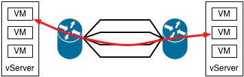
Four paths between routers, hashing headers chooses one.The UDP header serves an interesting purpose, it isn't there to perform the multiplexing role UDP normally serves. When switches have multiple paths available to a destination, whether an L2 trunk or L3 multipathing, the specific link is chosen by hashing packet headers. Most switch hardware is quite limited in how it computes the hash: the outermost L2/L3/L4 headers. Some chips can examine the inner headers of long-established tunneling protocols like GRE/MAC-in-MAC/IP-in-IP. For a new protocol like VXLAN, it would take years for silicon support for the inner headers to become common.
Therefore the VTEP calculates a hash of the inner packet headers, and places it in the source UDP port where it feeds into LACP/ECMP hash calculation. Existing switch chips get proper load balancing using only the Outer L2/L3/L4 headers, at the cost of 8 bytes of overhead.

VTEP calculates hash of inner packet headers, places it in the UDP source port.

New protocols sometimes encapsulate themselves inside UDP headers to more easily traverse firewalls and NAT devices. That isn't what VXLAN is doing, it would be somewhat ludicrous to put firewalls between subnets within a datacenter. In fact, the way VXLAN uses its UDP header can make firewall traversal a bit more challenging. The inner packet headers can hash to a well known UDP port number like 53, making it look like a DNS response, but a firewall attempting to inspect the contents of the frame will not find a valid DNS packet. It would be important to disable any deep packet inspection for packets traveling between VTEP endpoints. If VXLAN is used to extend an L2 network all the way across a WAN the firewall question becomes more interesting. I don't think its a good idea to have a VXLAN cross a WAN, but that will have to be a topic for another day.


VTEP Learning

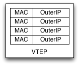
VTEP Table of MAC:OuterIP mappings.The VTEP examines the destination MAC address of frames it handles, looking up the IP address of the VTEP for that destination. This MAC:OuterIP mapping table is populated by learning, very much like an L2 switch discovers the port mappings for MAC addresses. When a VM wishes to communicate with another VM it generally first sends a broadcast ARP, which its VTEP will send to the multicast group for its VNI. All of the other VTEPs will learn the Inner MAC address of the sending VM and Outer IP address of its VTEP from this packet. The destination VM will respond to the ARP via a unicast message back to the sender, which allows the original VTEP to learn the destination mapping as well.
When a MAC address moves, the other VTEPs find its new location by the same learning process, using the first packet they see from its new VTEP. Why might a MAC address move? Consider a protocol like VRRP, which fails over a MAC address between two redundant servers. When ownership of a VRRP MAC address switches from one VM to another, all of the other VTEPs on the network need to learn the new MAC:OuterIP association. VRRP typically sends a gratuitous ARP when it fails over, and as a broadcast packet that ARP will be sent to all VTEPs. They learn the new MAC:OuterIP association from that packet.

VRRP nicely sends a gratuitous ARP when the MAC address moves, but not all MAC moves will do so. Consider the case where a running VM is frozen and moved to another server. The VM will resume where it left off, its ARP table fully populated for nodes it is communicating with. It won't send a gratuitous ARP because the VM has no idea that it has moved to a new vserver, and it won't send ARPs for addresses already in its table either. Its possible I've missed some subtlety, but I don't see how remote VTEPs would quickly learn the new location of the MAC address. I think they continue sending to the incorrect VTEP until their entries time out, and then they start flooding to the VXLAN multicast address.

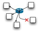
Multicast frame delivered to 3 VTEPs but dropped before reaching one.Though it is appealing to let VTEPs track each other automatically using multicast and learning, I suspect beyond a certain scale of network that isn't going to work very well. Multicast frames are not reliably delivered, and because they fan out to all nodes they tend to become ever less reliable as the number of nodes increases. The RFC mentions the possibility of other mechanisms to populate the VTEP tables, including centralized controllers. I suspect a controller will be an important product to offer. Troubleshooting why subsets of VMs transiently lose the ability to communicate after a move or failover would be really annoying. Small networks could rely on multicast, while larger networks could fall back to it if the controller fails.


Suggestions

On the off chance that people read this far, I'll offer a couple suggestions for modifications to the VXLAN specification based on discussion earlier in the article.

  • If VXLAN is used to connect remote facilities, it is likely to traverse firewalls. When the VTEP calculates a hash of the Inner headers to place in the UDP source port field, I'd recommend it always set the most significant bit. This restricts the hash to 15 bits, values 32768 - 65535, but avoids any low numbered port number with a defined meaning like DNS. This should still result in good LACP/ECMP hashing, as this makes VXLAN packets look like ephemeral ports used by UDP client applications.
  • When a VTEP sees a new source MAC address from a local VM, flood the packet even if the OuterIP of the destination is already known. This gives remote VTEPs a better chance of noticing a MAC move. The VTEP already had to keep track of local MAC addresses to properly deliver received frames, so I suspect there is already a local source learning function.

Next article: A few final VXLAN topics.


footnote: this blog contains articles on a range of topics. If you want more posts like this, I suggest the Ethernet label.

Friday, September 16, 2011

The Care and Feeding of VXLAN

This is the first of several articles about VXLAN. I have not been briefed by any of the companies involved, nor received any NDA information. These articles are written based on public statements and discussions available on the web.


Modern datacenter networks are designed around the requirements for virtualization. There are a number of physical servers connected to the network, each hosting a larger number of virtual servers. The Gentle Reader may be familiar with VMware on the desktop, with NAT to let VMs communicate with the Internet. Datacenter VMs don't work that way. Each VM has its own IP and MAC address, with software beneath the VMs to function as a switch. On the Ethernet we see a huge number of MAC addresses, from all of the VMs throughout the facility.

To rebalance server load it is necessary to support moving a virtual machine from a heavily loaded server to another more lightly loaded one. It is essentially impossible to change the IP address of a VM as part of this move. Though modern server OSes can change IP address without rebooting, doing so interrupts the service as client connections are closed and caches spread far and wide have to time out. To be useful, VM moves have to be mostly invisible and not interrupt services.

Datacenter networkmoving a VM from one physical server to another.

The most straightforward way to accomplish this is to have the servers sit in a single subnet and single broadcast domain, which leads to some truly enormous L2 networks. It is putting pressure on switch designs to support tens of thousands of MAC addresses (thankfully via hash engines, rather than CAMs). Everything we'd learned about networking to this point drove towards Layer3 networks for scalability, but it is all being rewritten for virtualized datacenters.


Enter VXLAN

At VMWorld several weeks ago there was an announcement of VXLAN, Virtual eXtensible LANs. I paid little attention at the time, but should have paid more. VXLAN is an encapsulation scheme to carry L2 frames atop L3 networks. Described like that it doesn't sound very interesting, but the details are well thought out. Additionally the RFC is authored by representatives from major virtualization vendors VMware, Citrix, and Red Hat, and by datacenter switch vendors Cisco and Arista. It will appear in real networks relatively quickly.

The bulk of the VXLAN implementation is handled via a tunneling endpoint. This will generally reside within the virtual server, in software running under the VMs. A new component called the VXLAN Tunnel End Point (VTEP) encapsulates frames inside an L3 tunnel. There can be 224 VXLANs, identified by a 24 bit VXLAN Network Identifier (VNI). The VTEP maintains a table of known destination MAC addresses, and stores the IP address of the tunnel to the remote VTEP to use for each. Unicast frames between VMs are sent directly to the unicast L3 address of the remote VTEP. Multicast and broadcast frames from VMs are sent to a multicast IP group associated with the VNI. The spec is vague on how VNIs map to a multicast IP address, merely saying that a management plane configures it along with VM membership in the VXLAN. Multicast distribution in most networks is something of an afterthought, making the address configurable allows VXLAN to cope with whatever facilities exist.

Overlay network connecting VMs through an L3 switch.


A Maze of Twisty Little Passages

VXLAN encapsulates L2 packets from the VMs within an Outer IP header to send across an IP network. The receiving VTEP decapsulates the packet, and consults the Inner headers to figure out how to deliver it to its destination.

Outer MAC, Outer IP, UDP, VXLAN, Inner MAC, Inner Payload, Outer FCS.

The encapsulated packet retains its Inner MAC header and optional Inner VLAN, but has no Inner CRC. When VMs send packets to other VMs within a server they do not calculate a CRC, one is added by a physical NIC when the packet leaves the server. As the VTEP is a software component within the server, prior to hitting any NIC, the frames have no CRC when the VTEP gets them. Therefore there is no integrity protection end to end, from the originating VM to receiving. This is another case where even on L2 networks, the Ethernet CRC does not work the way our intuition would suggest.

Next article: UDP


footnote: this blog contains articles on a range of topics. If you want more posts like this, I suggest the Ethernet label.

Sunday, September 4, 2011

Telling Strangers Where You Are

foursquare Ten One Hundred badge, for a thousand checkins.Not quite two years ago in this space I wrote about how I use foursquare. I've continued using the service since then, passing 1,000 checkins several months ago.

The first generation of location based services like foursquare have paid a lot of attention to privacy concerns. Explicit connection to other users is required in order to allow them to see your checkins. To do otherwise would have been perceived as creepy, the go-to label for vague privacy concerns. For those who do want to make their checkins public, Foursquare has an option to publish checkins to Twitter.

Yet social norms evolve, even in the span of just two years. Facebook Places and Google+ both offer checkins as a feature of their respective services. I've been periodically checking in on Google+ for several months. For routine trips I check in to a very limited circle of people, not so much out of concern about privacy as to not be spammy. For well-known venues I've been checking in publicly, and something fascinating happens: well-known venues are really well-known. Lots of people have been there, and they chime in with commentary and suggestions of things to see and do. Our trip to the Monterey Bay Aquarium was much improved by real-time suggestions from Google+ users, and pictures from the trip in turn made a couple other people think about going back.

Jeff Jarvis has long made the argument about the benefits of publicness, and that overemphasizing concerns about privacy undermines the benefits we could get by being connected. We use nebulous terms in justifying privacy like creepy, and stifle discussion of the value of openness. Our brains are really good at concocting (unlikely) scenarios of the bad things which could happen from sharing information, and not so good at seeing the good which can come of it. I'm definitely seeing that effect with public checkins, it seems scary but yet there is tremendous value in sharing them widely.


footnote: this blog contains articles on a range of topics. If you want more posts like this, I suggest the social label.


Friday, August 26, 2011

QFabric Conclusion

This is the fourth and final article in a series exploring the Juniper QFabric. Earlier articles provided an overview, a discussion of link speed, and musings on flow control. Juniper says the QFabric should not be thought of as a network but as one large distributed switch. This series examines techniques used in modular switch designs, and tries to apply them to the QFabric. This article attempts to cover a few loose ends, and wraps up the series.

As with previous days, the flow control post sparked an interesting discussion on Google+.


Whither Protocols?

Director connected to edge node and peered with another switchFor a number of years switch and router manufacturers competed on protocol support, implementing various extensions to OSPF/BGP/SpanningTree/etc in their software. QFabric is almost completely silent about protocols. In part this is a marketing philosophy: positioning the QFabric as a distributed switch instead of a network means that the protocols running within the fabric are an implementation detail, not something to talk about. I don't know what protocols are run between the nodes of the QFabric, but I'm sure its not Spanning Tree and OSPF.

Yet QFabric will need to connect to other network elements at its edge, where the datacenter connects to the outside world. Presumably the routing protocols it needs are implemented in the QF/Director and piped over to whichever switch ports connect to the rest of the network. If there are multiple peering points, they need to communicate with the same entity and a common routing information base.


Flooding Frowned Upon

The edge Nodes have an L2 table holding 96K MAC addresses. This reinforces the notion that switching decisions are made at the ingress edge, every Node can know how to reach destination MAC addresses at every port. There are a few options for distributing MAC address information to all of the nodes, but I suspect that flooding unknown addresses to all ports is not the preferred mechanism. If flooding is allowed at all, it would be carefully controlled.

Much of modern datacenter design revolves around virtualization. The VMWare vCenter (or equivalent) is a single, authoritative source of topology information for virtual servers. By hooking to the VM management system, the QFabric Director could know the expected port and VLAN for each server MAC address. The Node L2 tables could be pre-populated accordingly.

By hooking to the VM management console QFabric could also coordinate VLANs, flow control settings, and other network settings with the virtual switches running in software.


NetOps Force Multiplier

Where previously network engineers would be configuring dozens of switches, QFabric now proposes to manage a single distributed switch. Done well, this should be a substantial time saver. There will of course be cases where the abstraction leaks and the individual Nodes have to be dealt with. The failure modes in a distributed switch are simply different. Its unlikely that a single line card within a chassis will unexpectedly lose power, but its almost certain that Nodes occasionally will. Nonetheless, the cost to operate QFabric seems promising.


Conclusion

QFabric is an impressive piece of work, clearly the result of several years effort. Though the Interconnects use merchant silicon, Juniper almost certainly started working with the manufacturer at the start of the project to ensure the chip would meet their needs.

The most interesting part of QFabric is its flow control mechanism, for which Juniper has made some pretty stunning claims. A flow control mechanism with fairness, no packet loss, and quick reaction to changes over such a large topology is an impressive feat.


footnote: this blog contains articles on a range of topics. If you want more posts like this, I suggest the Ethernet label.


Thursday, August 25, 2011

QFabric: Flow Control Considered Harmful

This is the third in a series of posts exploring the Juniper QFabric. Juniper says the QFabric should not be thought of as a network but as one large distributed switch. This series examines techniques used in modular switch designs, and tries to apply them to the QFabric. This article focuses on link speeds.

Yesterday's post sparked an excellent discussion on Google+, disagreeing about overclocking of backplane links and suggesting LACP hashing as a reason for the requirement for 40 Gbps links. Ken Duda is a smart guy.


XON/XOFF

Ethernet includes (optional) link level flow control. An Ethernet device can signal its neighbor to stop sending traffic, requiring the neighbor to buffer packets until told it can resume sending. This flow control mechanism is universally implemented in the MAC hardware, not requiring software intervention on every flow control event.

Switch chip with one congested port flow controlling the entire linkThe flow control is for the whole link. For a switch with multiple downstream ports, there is no way to signal back to the sender that only some of the ports are congested. In this diagram, a single congested port requires the upstream to be flow controlled, even though the other port could accept more packets. Ethernet flow control suffers from head of line blocking, a single congested port will choke off traffic to other uncongested ports.

IEEE has tried to address this in two ways. Priority-based flow control, defined in IEEE 802.1Qbb, makes each of the eight classes of service flow control independently. Bulk data traffic would no longer block VoIP, for example. IEEE 802.1au is defining a congestion notification capability to send an explicit notification to compatible endstations, asking them to slow down. Per-priority pause is already appearing in some products. Congestion notification involves NICs and client operating systems, and is slower going.


QFabric

Juniper's whitepaper on QFabric has this to say about congestion:

Finally, the only apparent congestion is due to the limited bandwidth of ingress and egress interfaces and any congestion of egress interfaces does not affect ingress interfaces sending to non-congested interfaces; this noninterference is referred to as “non-blocking”

QFabric very clearly does not rely on Ethernet flow control for the links between edge nodes and interconnect, not even per-priority. It does something else, something which can reflect the queue state of an egress port on the far side of the fabric back to control the ingress. However, Juniper has said nothing that I can find about how this works. They rightly consider it part of their competitive advantage.

So... lets make stuff up. How might this be done?

Juniper has said that the Interconnect uses merchant switch silicon, but hasn't said anything about the edge nodes. As all the interesting stuff is done at the edge and Juniper has a substantial ASIC development capability, I'd assume they are using their own silicon there. Whatever mechanism they use for flow control would be implemented in the Nodes.

Most of the mechanisms I can think of require substantial buffering. QFX3500, the first QFabric edge node, has 4x40 Gbps ports connecting to the Interconnect. That is 20 gigabytes per second. A substantial bank of SRAM could buffer that traffic for a fraction of a second. For example, 256 Megabytes could absorb a bit over 13 milliseconds worth of traffic. 13 milliseconds provides a lot of time for real-time software to swing into action.

For example:

  • The memory could be used for egress buffering at the edge ports. Each Node could report its buffer status to all other nodes in the QFabric, several thousand times per second. Adding a few thousand packets per second from each switch is an insignificant load on the fabric. From there we can imagine a distributed flow control mechanism, which several thousand times per second would re-evaluate how much traffic it is allowed to send to each remote node in the fabric. Ethernet flow control frames could be sent to the sending edge port to slow it down.

    Or rather, smarter people than me can imagine how to construct a distributed flow control mechanism. My brain hurts just thinking about it.
  • Hardware counters could track the rate each Node is receiving traffic from each other Node, and software could report this several times per second. Part of the memory could be used as uplink buffering, with traffic shapers controlling the rate sent to each remote Node. Software could adjust the traffic shaping several thousand times per second to achieve fairness.

    Substantial uplink buffering also helps with oversubscribed uplinks. QFX3500 has 3:1 oversubscription.

I'll reiterate that the bullet points above are not how QFabric actually works, I made them up. Juniper isn't revealing how QFabric flow control works. If it achieves the results claimed it is a massive competitive advantage. I'm listing these to illustrate a point: a company willing to design and support its own switch silicon can take a wholly different approach from the rest of the industry. In the best case, they end up with an advantage for several years. In the worst case, they don't keep up with merchant silicon. I've been down both of those paths, the second is not fun.

There are precedents for the kind of systems described above: Infiniband reports queue information to neighbor IB nodes, and from this works out a flow control policy. Infiniband was designed in an earlier age when software wouldn't be able to handle the strict timing requirements, so it is defined in terms of hardware token buckets.

One thing I am sure of is that the QF/Director does not get involved in flow control. That would be a scalability and reliability problem. Juniper stated that the QFabric will continue to forward traffic even if the Director nodes have failed, the flow control mechanism cannot rely on the Directors.

Next article: wrap-up.


footnote: this blog contains articles on a range of topics. If you want more posts like this, I suggest the Ethernet label.


Wednesday, August 24, 2011

The Backplane Goes To Eleven

This is the second in a series of posts exploring the Juniper QFabric. Juniper says the QFabric should not be thought of as a network but as one large distributed switch. This series examines techniques used in modular switch designs, and tries to apply them to the QFabric. This article focuses on link speeds.


How Fast is Fast?

Ethernet link speeds are rigidly specified by the IEEE 802.3 standards, for example at 1/10/40/100/etc Gbps. It is important that Ethernet implementations from different vendors be able to interoperate.

Backplane links face fewer constraints, as there is little requirement for interoperability between implementations. Even if one wanted to it isn't possible to plug a card from one vendor into another vendor's chassis, they simply don't fit. Therefore backplane links within a chassis have been free to tweak their links speeds for better performance. In the 10 Gbps generation of products backplane links have typically run at 12.5 Gbps. In the 40 Gbps Ethernet generation I'd expect 45 or 50 Gbps backplane links (I don't really know, I no longer work in that space). A well-designed SERDES for a particular speed will have a bit of headroom, enabling faster operation over high quality links like a backplane. Running them faster tends to be possible without heroic effort.

Switch chip with 48 x 1Gbps downlinks and 4 x 10/12.5 Gbps uplinksA common spec for switch silicon in the 1Gbps generation is 48 x 1 Gbps ports plus 4 x 10 Gbps. Depending on the product requirements, 10 Gbps ports can be used for server attachment or as uplinks to build into a larger switch. At first glance the chassis application appears to be somewhat oversubscribed, with 48 Gbs of downlink but only 40 Gbps of uplink. In reality, when used in a chassis the uplink ports will run at 12.5 Gbps to get 50 Gbps of uplink bandwidth.

Though improved throughput and capacity is a big reason for running the backplane links faster, there is a more subtle benefit as well. Ethernet links are specified to run at some nominal clock frequency, modulo a tolerance measured in parts per million. The crystals driving the links can be slightly on the high or low side of the desired frequency yet still be within spec. If the backplane links happen to run slightly below nominal while the front panel links are slightly higher, the result would be occasional packet loss simply because the backplane cannot keep up. When a customer notices packet loss during stress tests in their lab it is very, very difficult to convince them it is expected and acceptable. Running the backplane links at a faster rate avoids the problem entirely, the backplane can always absorb line rate traffic from a front panel port.


QFabric

This is one area where QFabric takes a different tack from a modular chassis: I doubt the links between QF/Node and Interconnect are overclocked even slightly. In QFabric those links are not board traces they are lasers, and lasers are more picky about their data rate. In the Packet Pushers podcast the Juniper folks stated that the uplinks are required to be faster than the downlinks. That is, if the edge connections are 10 Gbps then the uplinks from Node to Interconnect have to be 40 Gbps. One reason for this is to avoid overruns due to clock frequency variance, and ensure the Interconnect can always absorb the link rate from an edge port without resorting to flow control.

Next article: flow control.


footnote: this blog contains articles on a range of topics. If you want more posts like this, I suggest the Ethernet label.


Tuesday, August 23, 2011

Making Stuff Up About QFabric

This is the first of several articles about the Juniper QFabric. I have not been briefed by Juniper, nor received any NDA information. These articles are written based on Juniper's public statements and materials available on the web, supplemented with details from a special Packet Pushers podcast, and topped off with a healthy amount of speculation and guessing about how it works.

Juniper QFabric with Nodes, Interconnect, and DirectorQFabric consists of edge nodes wired to two or four extremely large QF/Interconnect chassis, all managed via out of band links to QF/Directors. Juniper emphasizes that the collection of nodes, interconnects, and directors should be thought of as a single distributed switch rather than as a network. Packet handling within the QFabric is intended to be opaque, and the individual nodes are not separately configured. It is supposed to behave like one enormous, geographically distributed switch.

Therefore to try to brainstorm about how the distributed QFabric works we should think in terms of how a modular switch works, and how its functions might be distributed.


Exactly One Forwarding Decision

Ingress line card with switch fabric, connected to central supervisor with fabric, connected to egress line card with fabricModular Ethernet switches have line cards which can switch between ports on the card, with fabric cards (also commonly called supervisory modules, route modules, or MSMs) between line cards. One might assume that each level of switching would function like we expect Ethernet switches to work, forwarding based on the L2 or L3 destination address. There are a number of reasons why this doesn't work very well, most troublesome of which are the consistency issues. There is a delay between when a packet is processed by the ingress line card and the fabric, and between the fabric and egress. The L2 and L3 tables can change between the time a packet hits one level of switching and the next, and its very, very hard to design a robust switching platform with so many corner cases and race conditions to worry about.

Control header prepended to frameTherefore all Ethernet switch silicon I know of relies on control headers prepended to the packet. A forwarding decision is made at exactly one place in the system, generally either the ingress line card or the central fabric cards. The forwarding decision includes any rewrites or tunnel encapsulations to be done, and determines the egress port. A header is prepended to the packet for the rest of its trip through the chassis, telling all remaining switch chips what to do with it. To avoid impacting the forwarding rate, these headers replace part of the Ethernet preamble.

Control header prepended to frameGenerally the chips are configured to use these prepended control headers only on backplane links, and drop the header before the packet leaves the chassis. There are some exceptions where control headers are carried over external links to another box. Several companies sell variations on the port extender, a set of additional ports to be controlled remotely by a chassis switch. The link to the port extender will carry the control headers which would otherwise be restricted to the backplane. Similarly, several vendors sell stackable switches. Each unit in the stack can function as an independent switch, but can be connected via stack ports on the back to function together like a larger switch. The stack ports carry the prepended control headers from one stack member to the next, so the entire collection can function like a single forwarding plane.


QFabric

In the Packet Pushers podcast and in an article on EtherealMind, the Interconnect is described as a Clos network with stages of the Clos implemented in cards in the front and back of the chassis. It is implemented using merchant silicon, not Juniper ASICs. The technology in the edge Node was not specified, it is my assumption that Juniper uses its own silicon there.

Forwarding decisions are made in the Nodes and sent to the Interconnect, which is is a pure fabric with no decision making. This would be implemented by having the Nodes send control headers on their uplinks, in a format compatible with whatever merchant silicon is used in the Interconnect plus additional information needed to support the QFabric features. Juniper would not allow themselves to be locked in to a particular chip supplier, I'm sure the QF/Node implementation would be very flexible in how it creates those headers. A new QF/Interconnect with a different chipset would be supportable via a firmware upgrade to the edge nodes.

The QF/Interconnect would in turn forward the packet to its destination with the control header intact. The destination switch would perform whatever handling was indicated in the control information, discard the extra header, and forward the packet out the egress port.


Oversubscribed QF/Nodes

One interesting aspect of the first generation QF/Node is that it is oversubscribed. The QFX3500 has 480 Gbps of downlink capacity, in the form of 48 x 10G ports. It has 160 Gbps of uplink, via 4 x 40Gbps ports. Oversubscribed line cards are not unheard of in module chassis architectures, though it is generally the result of a followon generation of cards outstrips the capacity of the backplane. There have been chassis designs where the line cards were deliberately oversubscribed, but they are somewhat less common.

QFabric has a very impressive system to handle congestion and flow control, which will be the topic of a future article. The oversubscribed uplink is a slightly different variation, but in the end is really another form of congestion for the fabric to deal with. It would buffer what it can, and assert Ethernet flow control and/or some other means of backpressure to the edge ports if necessary.

Next article: link speeds.


footnote: this blog contains articles on a range of topics. If you want more posts like this, I suggest the Ethernet label.


Sunday, August 21, 2011

Consistency At All Levels

Twitter now wraps all links passing through the service with the t.co link shortener, which I wondered about a little while ago. Twitter engineers sweat the details, even the HTTP response headers are concise:

$ curl --head http://t.co/WXZtRHC
HTTP/1.1 301 Moved Permanently
Date: Sun, 21 Aug 2011 12:17:43 GMT
Server: hi
Location: http://codingrelic.geekhold.com/2011/07/tweetalytics.html
Cache-Control: private,max-age=300
Expires: Sun, 21 Aug 2011 12:22:43 GMT
Connection: close
Content-Type: text/html; charset=UTF-8

Oh, hi. Um, how are you?


Monday, August 15, 2011

An Awkward Segue to CPU Caching

Last week Andy Firth published The Demise of the Low Level Programmer, expressing dismay over the lack of low level systems knowledge displayed by younger engineers in the console game programming field. Andy's particular concerns deal with proper use of floating versus fixed point numbers, CPU cache behavior and branch prediction, bit manipulation, etc.

I have to admit a certain sympathy for this position. I've focussed on low level issues for much of my career. As I'm not in the games space, the specific topics I would offer differ somewhat: cache coherency with I/O, and page coloring, for example. Nonetheless, I feel a certain solidarity.

Yet I don't recall those topics being taught in school. I had classes which covered operating systems and virtual memory, but distinctly remember being shocked at the complications the first time I encountered a system which mandated page coloring. Similarly though I had a class on assembly programming, by the time I actually needed to work at that level I had to learn new instruction sets and many techniques.

In my experience at least, schools never did teach such topics. This stuff is learned by doing, as part of a project or on the job. The difference now is that fewer programmers are learning it. Its not because programmers are getting worse. I interview a lot of young engineers, their caliber is as high as I have ever experienced. It is simply that computing has grown a great deal in 20 years, there are a lot more topics available to learn, and frankly the cutting edge stuff has moved on. Even in the gaming space which spurred Andy's original article, big chunks of the market have been completely transformed. Twenty years ago casual gaming meant Game Boy, an environment so constrained that heroic optimization efforts were required. Now casual gaming means web based games on social networks. The relevant skill set has changed.

I'm sure Andy Firth is aware of the changes in the industry. Its simply that we have a tendency to assume that markets where there is a lot of money being made will inevitably attract new engineers, and so there should be a steady supply of new low level programmers for consoles. Unfortunately I don't believe that is true. Markets which are making lots of money don't attract young engineers. Markets which are perceived to be growing do, and other parts of the gaming market are perceived to be growing faster.


Page Coloring

Least significant bits as cache line offset, next few bits as cache indexBecause I brought it up earlier, we'll conclude with a discussion of page coloring. I am not satisfied with the Wikipedia page, which seems to have paraphrased a FreeBSD writeup describing page coloring as a performance issue. In some CPUs, albeit not current mainstream CPUs, coloring isn't just a performance issue. It is essential for correct operation.


Cache Index

Least significant bits as cache line offset, next few bits as cache indexBefore fetching a value from memory the CPU consults its cache. The least significant bits of the desired address are an offset into the cache line, generally 4, 5, or 6 bits for a 16/32/64 byte cache line.

The next few bits of the address are an index to select the cache line. It the cache has 1024 entries, then ten bits would be used as the index. Things get a bit more complicated here due to set associativity, which lets entries occupy several different locations to improve utilization. A two way set associative cache of 1024 entries would take 9 bits from the address and then check two possible locations. A four way set associative cache would use 8 bits. Etc.


Page tag

Least significant bits as page offset, upper bits as page tagSeparately, the CPU defines a page size for the virtual memory system. 4 and 8 Kilobytes are common. The least significant bits of the address are the offset within the page, 12 or 13 bits for 4 or 8 K respectively. The most significant bits are a page number, used by the CPU cache as a tag. The hardware fetches the tag of the selected cache lines to check against the upper bits of the desired address. If they match, it is a cache hit and no access to DRAM is needed.

To reiterate: the tag is not the remaining bits of the address above the index and offset. The bits to be used for the tag are determined by the page size, and not directly tied to the details of the CPU cache indexing.


Virtual versus Physical

In the initial few stages of processing the load instruction the CPU has only the virtual address of the desired memory location. It will look up the virtual address in its TLB to get the physical address, but using the virtual address to access the cache is a performance win: the cache lookup can start earlier in the CPU pipeline. Its especially advantageous to use the virtual address for the cache index, as that processing happens earlier.

The tag is almost always taken from the physical address. Virtual tagging complicates shared memory across processes: the same physical page would have to be mapped at the same virtual address in all processes. That is an essentially impossible requirement to put on a VM system. Tag comparison happens later in the CPU pipeline, when the physical address will likely be available anyway, so it is (almost) universally taken from the physical address.

This is where page coloring comes into the picture.


Virtually Indexed, Physically Tagged

From everything described above, the size of the page tag is independent of the size of the cache index and offset. They are separate decisions, and frankly the page size is generally mandated. It is kept the same for all CPUs in a given architectural family even as they vary their cache implementations.

Consider then, the impact of a series of design choices:

  • 32 bit CPU architecture
  • 64 byte cache line: 6 bits of cache line offset
  • 8K page size: 19 bits of page tag, 13 bits of page offset
  • 512 entries in the L1 cache, direct mapped. 9 bits of cache index.
  • virtual indexing, for a shorter CPU pipeline. Physical tagging.
  • write back
Virtually indexed, physically tagged, with 2 bits of page color

What does this mean? It means the lower 15 bits of the virtual address and the upper 19 bits of the physical address are referenced while looking up items in the cache. Two of the bits overlap between the virtual and physical addresses. Those two bits are the page color. For proper operation, this CPU requires that all processes which map in a particular page do so at the same color. Though in theory the page could be any color so long as all mappings are the same, in practice the virtual color bits are set the same as the underlying physical page.

The impact of not enforcing page coloring is dire. A write in one process will be stored in one cache line, a read from another process will access a different cache line.

Page coloring like this places quite a burden on the VM system, and one which would be difficult to retrofit into an existing VM implementation. OS developers would push back against new CPUs which proposed to require coloring, and you used to see CPU designs making fairly odd tradeoffs in their L1 cache because of it. HP PA-RISC used a very small (but extremely fast) L1 cache. I think they did this to use direct mapped virtual indexing without needing page coloring. There were CPUs with really insane levels of set associativity in the L1 cache, 8 way or even 16 way. This reduced the number of index bits to the point where a virtual index wouldn't require coloring.