This is the third in a series of posts exploring the Juniper QFabric. Juniper says the QFabric should not be thought of as a network but as one large distributed switch. This series examines techniques used in modular switch designs, and tries to apply them to the QFabric. This article focuses on link speeds.
Yesterday's post sparked an excellent discussion on Google+, disagreeing about overclocking of backplane links and suggesting LACP hashing as a reason for the requirement for 40 Gbps links. Ken Duda is a smart guy.
XON/XOFF
Ethernet includes (optional) link level flow control. An Ethernet device can signal its neighbor to stop sending traffic, requiring the neighbor to buffer packets until told it can resume sending. This flow control mechanism is universally implemented in the MAC hardware, not requiring software intervention on every flow control event.
 The flow control is for the whole link. For a switch with multiple downstream ports, there is no way to signal back to the sender that only some of the ports are congested. In this diagram, a single congested port requires the upstream to be flow controlled, even though the other port could accept more packets. Ethernet flow control suffers from head of line blocking, a single congested port will choke off traffic to other uncongested ports.
IEEE has tried to address this in two ways. Priority-based flow control, defined in IEEE 802.1Qbb, makes each of the eight classes of service flow control independently. Bulk data traffic would no longer block VoIP, for example. IEEE 802.1au is defining a congestion notification capability to send an explicit notification to compatible endstations, asking them to slow down. Per-priority pause is already appearing in some products. Congestion notification involves NICs and client operating systems, and is slower going.
QFabric
Juniper's whitepaper on QFabric has this to say about congestion:
Finally, the only apparent congestion is due to the limited bandwidth of ingress and egress interfaces and any congestion of egress interfaces does not affect ingress interfaces sending to non-congested interfaces; this noninterference is referred to as “non-blocking”
QFabric very clearly does not rely on Ethernet flow control for the links between edge nodes and interconnect, not even per-priority. It does something else, something which can reflect the queue state of an egress port on the far side of the fabric back to control the ingress. However, Juniper has said nothing that I can find about how this works. They rightly consider it part of their competitive advantage.
So... lets make stuff up. How might this be done?
Juniper has said that the Interconnect uses merchant switch silicon, but hasn't said anything about the edge nodes. As all the interesting stuff is done at the edge and Juniper has a substantial ASIC development capability, I'd assume they are using their own silicon there. Whatever mechanism they use for flow control would be implemented in the Nodes.
Most of the mechanisms I can think of require substantial buffering. QFX3500, the first QFabric edge node, has 4x40 Gbps ports connecting to the Interconnect. That is 20 gigabytes per second. A substantial bank of SRAM could buffer that traffic for a fraction of a second. For example, 256 Megabytes could absorb a bit over 13 milliseconds worth of traffic. 13 milliseconds provides a lot of time for real-time software to swing into action.
For example:
- The memory could be used for egress buffering at the edge ports. Each Node could report its buffer status to all other nodes in the QFabric, several thousand times per second. Adding a few thousand packets per second from each switch is an insignificant load on the fabric. From there we can imagine a distributed flow control mechanism, which several thousand times per second would re-evaluate how much traffic it is allowed to send to each remote node in the fabric. Ethernet flow control frames could be sent to the sending edge port to slow it down.
Or rather, smarter people than me can imagine how to construct a distributed flow control mechanism. My brain hurts just thinking about it. - Hardware counters could track the rate each Node is receiving traffic from each other Node, and software could report this several times per second. Part of the memory could be used as uplink buffering, with traffic shapers controlling the rate sent to each remote Node. Software could adjust the traffic shaping several thousand times per second to achieve fairness.
Substantial uplink buffering also helps with oversubscribed uplinks. QFX3500 has 3:1 oversubscription.
I'll reiterate that the bullet points above are not how QFabric actually works, I made them up. Juniper isn't revealing how QFabric flow control works. If it achieves the results claimed it is a massive competitive advantage. I'm listing these to illustrate a point: a company willing to design and support its own switch silicon can take a wholly different approach from the rest of the industry. In the best case, they end up with an advantage for several years. In the worst case, they don't keep up with merchant silicon. I've been down both of those paths, the second is not fun.
There are precedents for the kind of systems described above: Infiniband reports queue information to neighbor IB nodes, and from this works out a flow control policy. Infiniband was designed in an earlier age when software wouldn't be able to handle the strict timing requirements, so it is defined in terms of hardware token buckets.
One thing I am sure of is that the QF/Director does not get involved in flow control. That would be a scalability and reliability problem. Juniper stated that the QFabric will continue to forward traffic even if the Director nodes have failed, the flow control mechanism cannot rely on the Directors.
Next article: wrap-up.
footnote: this blog contains articles on a range of topics. If you want more posts like this, I suggest the Ethernet label.
 A common spec for switch silicon in the 1Gbps generation is 48 x 1 Gbps ports plus 4 x 10 Gbps. Depending on the product requirements, 10 Gbps ports can be used for server attachment or as uplinks to build into a larger switch. At first glance the chassis application appears to be somewhat oversubscribed, with 48 Gbs of downlink but only 40 Gbps of uplink. In reality, when used in a chassis the uplink ports will run at 12.5 Gbps to get 50 Gbps of uplink bandwidth.
 QFabric consists of edge nodes wired to two or four extremely large
  Modular Ethernet switches have line cards which can switch between ports on the card, with fabric cards (also commonly called supervisory modules, route modules, or MSMs) between line cards. One might assume that each level of switching would function like we expect Ethernet switches to work, forwarding based on the L2 or L3 destination address. There are a number of reasons why this doesn't work very well, most troublesome of which are the consistency issues. There is a delay between when a packet is processed by the ingress line card and the fabric, and between the fabric and egress. The L2 and L3 tables can change between the time a packet hits one level of switching and the next, and its very, very hard to design a robust switching platform with so many corner cases and race conditions to worry about.
 Therefore all Ethernet switch silicon I know of relies on control headers prepended to the packet. A forwarding decision is made at exactly one place in the system, generally either the ingress line card or the central fabric cards. The forwarding decision includes any rewrites or tunnel encapsulations to be done, and determines the egress port. A header is prepended to the packet for the rest of its trip through the chassis, telling all remaining switch chips what to do with it. To avoid impacting the forwarding rate, these headers replace part of the
  Generally the chips are configured to use these prepended control headers only on backplane links, and drop the header before the packet leaves the chassis. There are some exceptions where control headers are carried over external links to another box. Several companies sell variations on the
  Because I brought it up earlier, we'll conclude with a discussion of page coloring. I am not satisfied with the
  Before fetching a value from memory the CPU consults its cache. The least significant bits of the desired address are an offset into the cache line, generally 4, 5, or 6 bits for a 16/32/64 byte cache line.
 Separately, the CPU defines a page size for the virtual memory system. 4 and 8 Kilobytes are common. The least significant bits of the address are the offset within the page, 12 or 13 bits for 4 or 8 K respectively. The most significant bits are a page number, used by the CPU cache as a tag. The hardware fetches the tag of the selected cache lines to check against the upper bits of the desired address. If they match, it is a cache hit and no access to DRAM is needed.
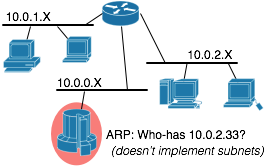
 Consider a network using traditional L3 routing: you give each subscriber an IP address on their own IP subnet. You need to have a router address on the same subnet, and you need a broadcast address. Needing 3 IPs per subscriber means a /30. Thats 4 IP addresses allocated per customer.

 Until this week I thought Twitter
  My current project relies on a large number of

 In a typical datacenter, the servers sit behind a load balancer. The simplest such equipment distributes sessions without modifying the packets, but the market demands
 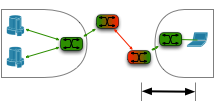 High speed wide area networks are expensive. If a one-time purchase of a magic box at each end can reduce the monthly cost of the connection between them, then there is an economic benefit to buying the magic box.
  Organizations set up HTTP proxies to enforce security policies, cache content, and a host of other reasons.