Friday, October 30, 2009

Disallow:/tricks

This is cute, pointed out in a tweet by Matt Cutts. There is a Halloween easter egg in Google's robots.txt file.

Disallow: /errors/
Disallow: /voice/fm/
Disallow: /voice/media/
Disallow: /voice/shared/
Disallow: /app/updates

User-agent: Kids
Disallow: /tricks
Allow: /treats

Sitemap: http://www.gstatic.com/s2/...

Sadly neither /tricks nor /treats actually exists.

Monday, October 26, 2009

Current GMail Ads

Here are the ads currently showing in my GMail:

Insomnia Ads in GMail

I wonder what they are trying to tell me...

Friday, October 23, 2009

ARM Cortex A5

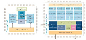
On October 21 ARM announced a new CPU design at the low end of their range, the Cortex A5. It is intended to replace the earlier ARM7, ARM9, and ARM11 parts. The A5 can have up to 4 cores, but given its positioning as the smallest ARM the single core variant will likely dominate.

To me the most interesting aspect of this announcement is that when the Cortex A5 ships (in 2011!) all ARM processors, regardless of price range, will have an MMU. The older ARM7TDMI relied on purely physical addressing, necessitating the use of either uClinux, vxWorks, or a similar RTOS. With the ARM Cortex processor family any application requiring a 32 bit CPU will have the standard Linux kernel as an option.

Story first noted at Ars Technica

Cortex A5

 
Update

In the comments Dave Cason and Brooks Moses point out that I missed the ARM Cortex-M range of processors, which are considerably smaller than the Cortex-A. The Cortex-Ms do not have a full MMU, though some parts in the range have a memory protection unit. So it is not the case that all ARM processors will now have MMUs. Mea culpa.

Monday, October 19, 2009

Tweetravenous Solutions

Recently Rob Diana wrote a guest post at WorkAwesome, Balancing Work And Social Media Addiction. In it, he said:

"If your day job is sitting in a cube or corporate office somewhere, then you will need to limit your activity in some way. If you want to be like Robert Scoble or Louis Gray, you will have to give up some sleep to stay active on several sites."

Twitter Skin Patch We at Tweetravenous Solutions have another solution to offer, which allows our customers to handle a full day's work, a full day of social media, and still get a full night's sleep! We call it the Social Media Patch. Our patented algorithms will monitor your social media feeds, collating and condensing updates from those you follow and encoding them in a complex matrix of proteins, amino acids, and caffeine. Its all infused into an easy-to-apply skin patch which can be worn inconspicuously beneath clothing. Even better, its in Real Time! (note1)


Social Media Skin patches for twitter, friendfeed, and RSS.  

Never go without your twitter fix again!

Feed your friendfeed need!

Works with any RSS feed, too! (note2)


Wait, there's more! For the true Social Media Expert wanting to get an edge on the competition, we offer additional treatment options administered in our state-of-the-art facility!
Twitter IV drip

Coming soon: two way communication! Thats right, you'll be able to retweet or reply using only the power of your mind! (and bodily secretions) (note3)


Don't wait, call now!


note1: Real Time is defined as 48 hours, to allow for processing and express overnight delivery.

note2: pubsubhubbub and rssCloud support coming soon.

note3: Two way communication will incur additional cost, and add processing time. US Postal Service will not accept bodily secretions for delivery.


Author's note: I enjoyed Rob Diana's article, and recommend people to read it. When I saw "Social Media Addiction" in its title, the thought of a Nicotine patch came spontaneously to mind. It became a moral imperative to write this up.

Also: sadly, modern browsers no longer render the <blink> tag. Too bad, it would have been sweet.


Wednesday, October 14, 2009

AMD IOMMU: Missed Opportunity?

In 2007 AMD implemented an I/O MMU in their system architecture, which translates DMA addresses from peripheral devices to a different address on the system bus. There were several motivations for doing this:

    Direct Virtual Memory Access
  1. Virtualization: DMA can be restricted to memory belonging to a single VM and to use the addresses from that VM, making it safe for a driver in that VM to take direct control of the device. This appears to be the largest motivation for adding the IOMMU.
  2. High Memory support: For I/O buses using 32 bit addressing, system memory above the 4GB mark is inaccessible. This has typically been handled using bounce buffers, where the hardware DMAs into low memory which the software will then copy to its destination. An IOMMU allows devices to directly access any memory in the system, avoiding copies. There are a large number of PCI and PCI-X devices limited to 32 bit DMA addresses. Amazingly, a fair number of PCI Express devices are also limited to 32 bit addressing, probably because they repackage an older PCI design with a new interface.
  3. Enable user space drivers: A user space application has no knowledge of physical addresses, making it impossible to program a DMA device directly. The I/O MMU can remap the DMA addresses to be the same as the user process, allowing direct control of the device. Only interrupts would still require kernel involvement.

 
I/O Device Latency

Multiple levels of bus bridging PCIe has a very high link bandwidth, making it easy to forget that its position in the system imposes several levels of bridging with correspondingly long latency to get to memory. The PCIe transaction first traverses the Northbridge and any internal switching or bus bridging it contains, on its way to the processor interconnect. The interconnect is HyperTransport for AMD CPUs, and QuickPath for Intel. Depending on the platform, the transaction might have to travel through multiple CPUs before it reaches its destination memory controller, where it can finally access its data. A PCIe Read transaction must then wend its way back through the same path to return the requested data.

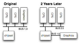
Graphics device on CPU bus

Much lower latency comes from sitting directly on the processor bus, and there have been systems where I/O devices sit directly beside CPUs. However CPU architectures rev that bus more often than it is practical to redesign a horde of peripherals. Attempts to place I/O devices on the CPU bus generally result in a requirement to maintain the "old" CPU bus as an I/O interface on the side of the next system chipset, to retain the expensive peripherals of the previous generation.


The Missed Opportunity: DMA Read pipelining

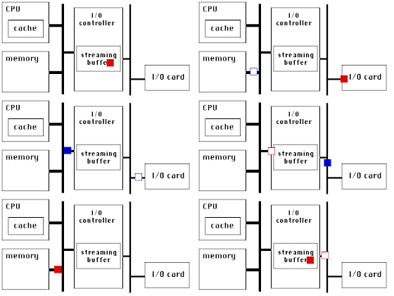
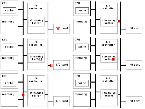
An IOMMU is not a new concept. Sun SPARC, some SGI MIPS systems, and Intel's Itanium all employ them. Once you have taken the plunge to impose an address lookup between a DMA device and the rest of the system, there are other interesting things you can do in addition to remapping. For example, you can allow the mapping to specify additional attributes for the memory region. Knowing whether it is likely to do long, contiguous bursts or short concise updates allows optimizations to reduce latency by reading ahead, to transfer data faster by pipelining.

Without prefetch (CONSISTENT) With prefetch (STREAMING)
DMA Read with no prefetch DMA Read with prefetch

AMD's IOMMU includes nothing like this. Presumably they wanted to confine the software changes to the Hypervisor alone, whilst choosing STREAMING versus CONSISTENT requires support in the driver of the device initiating DMA, but they could have ensured software compatibility by making CONSISTENT be the default with STREAMING only used by drivers which choose to implement it.


What About Writes?

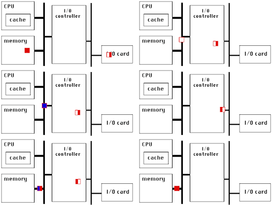
The IOMMU in SPARC systems implemented additional support for DMA write operations. Writing less than a cache line is inefficient, as the I/O controller has to fetch the entire line from memory and merge the changes before writing it back. This was a problem for Sun, which had a largish number of existing SBus devices issuing 16 or 32 byte writes while the SPARC cache line had grown to 64 bytes. A STREAMING mapping relaxed the requirement for instantaneous consistency: if a burst wrote the first part of a cache line, the I/O controller was allowed to buffer it in hopes that subsequent DMA operations would fill in the rest of the line. This is an idea whose time has come... and gone. The PCI spec takes great care to emphasize cache line sized writes using MWL or MWM, an emphasis which carries over the PCIe as well. There is little reason now to design coalescing hardware to optimize sub-cacheline writes.

Without buffering (CONSISTENT) With buffering (STREAMING)
DMA Write with no prefetch DMA Write with prefetch

 
Closing Disclaimer

Maybe I'm way off base in lamenting the lack of DMA read pipelining. Maybe all relevant PCIe devices always issue Memory Read Multiple requests for huge chunks of data, and the chipset already pipelines data fetch during such large transactions. Maybe. I doubt it, but maybe...

Tuesday, October 13, 2009

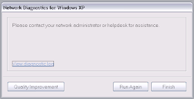
WinXP Network Diagnostic

Please contact your network administrator or helpdesk

Thanks, but I could probably have figured that out without help from the diagnostic utility.

Sunday, October 11, 2009

A Cloud Over the Industry

Unbelievable:

Regrettably, based on Microsoft/Danger's latest recovery assessment of their systems, we must now inform you that personal information stored on your device - such as contacts, calendar entries, to-do lists or photos - that is no longer on your Sidekick almost certainly has been lost as a result of a server failure at Microsoft/Danger. That said, our teams continue to work around-the-clock in hopes of discovering some way to recover this information. However, the likelihood of a successful outcome is extremely low.

This kind of monumental failure casts a cloud over the entire industry (pun intended). How did it happen? I do not believe Danger could have operated without sufficient redundancy and without backups for so many years, it simply does not pass the smell test. There must be more to the story.

On possible theory for unrecoverable loss of all customer data is actually sabotage by a disgruntled insider. This is, itself, pretty unbelievable. Nonetheless according to GigaOM, when Microsoft acquired Danger "...while some of the early investors got modest returns, I am told that the later-stage investors made out like bandits." I wonder if the early employees also made only a modest payout in return for their years of effort, and had to watch the late stage investors take everything. Danger filed for IPO in late 2007, but was suddenly acquired by Microsoft in early 2008. What if the investors determined they would not make as much money in a large IPO as they would in a carefully arranged, smaller acquisition by Microsoft? For example, the term sheet might have included a substantial liquidation preference but specify that all shares revert to common if the exit is above N dollars. For the investors, the best exit is (N-1) dollars; they maximize their return by keeping a larger fraction of a smaller pie. If they had drag along rights, they could force the acquisition over the objections of employees and management. If the long-time employees watched their payday be snatched away... a workforce of disgruntled employees seems quite plausible.

This is all, of course, complete speculation on my part. I simply cannot believe that the company could accidentally lose all data, for all customers, irrevocably. It doesn't make sense.

Danger Sidekick

Other links relating to this story:

Thursday, October 8, 2009

Code Snippet: SO_BINDTODEVICE

In a system with multiple network interfaces, can you constrain a packet to go out one specific interface? If you answered "bind() the socket to an address," you should read on.

Why might one need to strictly control where packets can be routed? The best use case I know is when ethernet is used as a control plane inside a product. Packets intended to go to another card within the chassis must not, under any circumstances, leave the chassis. You don't want bugs or misconfiguration to result in leaking control traffic.

The bind() system call is frequently misunderstood. It is used to bind to a particular IP address. Only packets destined to that IP address will be received, and any transmitted packets will carry that IP address as their source. bind() does not control anything about the routing of transmitted packets. So for example, if you bound to the IP address of eth0 but you send a packet to a destination where the kernel's best route goes out eth1, it will happily send the packet out eth1 with the source IP address of eth0. This is perfectly valid for TCP/IP, where packets can traverse unrelated networks on their way to the destination.

In Linux, to control the physical topology of communication you use the SO_BINDTODEVICE socket option.

#include <netinet/in.h>
#include <net/if.h>
#include <sys/ioctl.h>
#include <sys/types.h>
#include <sys/socket.h>

int main(int argc, char **argv)
{
    int s;
    struct ifreq ifr;

    if ((s = socket(AF_INET, SOCK_STREAM, 0)) < 0) {
        ... error handling ...
    }

    memset(&ifr, 0, sizeof(ifr));
    snprintf(ifr.ifr_name, sizeof(ifr.ifr_name), "eth0");
    if (setsockopt(s, SOL_SOCKET, SO_BINDTODEVICE,
                (void *)&ifr, sizeof(ifr)) < 0) {
        ... error handling ...
    }

SO_BINDTODEVICE forces packets on the socket to only egress the bound interface, regardless of what the IP routing table would normally choose. Similarly only packets which ingress the bound interface will be received on the socket, packets from other interfaces will not be delivered to the socket.

There is no particular interaction between bind() and SO_BINDTODEVICE. It is certainly possible to bind to the IP address of the interface to which one will also SO_BINDTODEVICE, as this will ensure that the packets carry the desired source IP address. It is also permissible, albeit weird, to bind to the IP address of one interface but SO_BINDTODEVICE a different interface. It is unlikely that any ingress packets will carry the proper combination of destination IP address and ingress interface, but for very special use cases it could be done.

Monday, October 5, 2009

Captcha Text Wrong?


Captcha Not Available

I typed it exactly, even the capitalization.

Thursday, October 1, 2009

Yield to Your Multicore Overlords

ASIC design is all about juggling multiple competing requirements. You want to make the chip competitive by increasing its capabilities, by reducing its price, or both. Today we'll focus on the second half of that tradeoff, reducing the price.

Chip fabrication is a statistical game: of the parts coming off the fab, some percentage simply do not work. The vendor runs test vectors against the chips, and throws away the ones which fail. This is called the yield, and is the primary factor determining the cost of the chip. If the yield is bad, so you have to fab a whole bunch of chips to get one that actually works, you have to charge more for that one working chip.

To illustrate why most chips coming out of the fab do not work, I'd like to walk through part of manufacturing a chip. This information is from 1995 or so, when I was last seriously involved in a chip design, and describes a 0.8 micron process. So it is completely old and busted, but is sufficient for our purposes here.

Begin by placing the silicon wafer in a nitrogen atmosphere. You deposit a photo-resist on the wafer, basically a goo which hardens when exposed to ultraviolet light. You place a shadow mask in front of a light source; the regions exposed to light will harden while those under the shadow mask remain soft. You then chemically etch off the soft regions of the photo-resist, leaving exposed silicon where they were. The hardened regions of photo-resist stay put.

Next you heat the wafer to 400 degrees and pipe phosphorous into the nitrogen atmosphere. As the K atoms heat they begin moving faster and bouncing off the walls of the chamber. Some of them move fast enough that when they strike the surface of the wafer they break the Si crystal lattice and embed themselves in the silicon. If they strike the hardened photo-resist, they embed themselves in the resist; very, very few are moving fast enough to crash all the way through the photoresist into the silicon underneath.

Electron Microscopy image of a silicon die

Next you use a different chemical process to strip off the hardened photoresist. You are left with a wafer which has phosphorous embedded in the places you wanted. Now you heat the wafer even higher, hot enough that the silicon atoms can move around more freely; they move back into position and reform the crystal lattice, burying the phosphorous atoms embedded within. This is called annealing. Now you have the p+ regions of the transistors.

You repeat this process with aluminum ions to get the n- regions. Now you have transistors. Next you connect the transistors together with traces of aluminum (which I won't go into here). You cut the wafer to separate the die, and place each die in a package. You connect bonding wires from the edge of the die to the pins of the chip. And voila, you're done.


It should be apparent that this is a probabalistic process. Sometimes, based purely on random chance, not enough phosphorous atoms embed themselves into the silicon and your transistors don't turn on. Sometimes too much phosphorous embeds and your transistors won't turn off. Sometimes the Si lattice is too badly damaged and the annealing is ineffective. Sometimes the metal doesn't line up with the vias. Sometimes a dust particle lands on the chip and you deposit metal on top of the dust mote. Sometimes the bonding doesn't line up with the pads. Etc etc.

This is why the larger a chip grows, the more expensive it becomes. Its not because raw silicon wafers are particularly costly, its that the probability of there being a defect somewhere grows ever greater as the die becomes larger. The bigger the chip, the lower the yield of functional parts.

Intel Nehalem chip with SRAM highlited For at least 15 years that I know of, chip designs have improved their yield using redundancy. The earliest such efforts were done in on-chip memory: if your chip is supposed to include N banks of SRAM, put N+1 banks on the die connected with wires in the top most layer which can be cut using a laser. The SRAM occupies a large percentage of the total chip area, statistically it is likely that defects will be within the SRAM. You can then cut out the defective bank, and turn a defective chip into one that can be used. More recent silicon processes use fuses blown by the test fixture instead of lasers.


Massively Multicore Processors

Yesterday NVidia announced Fermi, a beast of a chip with 512 Cuda GPU cores. They are arranged in 16 blocks of 32 cores each. At this kind of scale, I suspect it makes sense to include extra cores in the design to improve the yield. For example, perhaps each block actually has 33 cores in the silicon so that a defective core can be tolerated.

In order to avoid having weird performance variations in the product, the extra resources are generally inaccessible if not used for yield improvement. That is even though the chip might have 528 cores physically present, no more than 512 could ever be used.
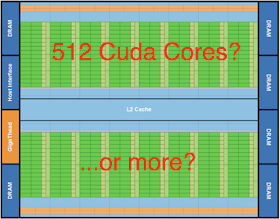
NVidia Fermi GPU